

Every Bluetooth Low Energy (Bluetooth LE) product has to work through enclosures and building materials. But how much signal do they actually block? If you’re designing a sensor inside a plastic enclosure or a tracker behind a metal panel, you need real numbers, not guesses.
I’ve seen plenty of generic “RF attenuation” charts online, but most cite vague ranges without specifying the frequency or test methodology. For Bluetooth LE developers working at 2.4 GHz, that’s not good enough. So I decided to measure it myself, inside a calibrated RF shielded chamber, with a repeatable test setup. Let’s take a look at what the data shows.
In this post, we’ll cover:
- Why material attenuation matters for Bluetooth LE product design
- The test setup: how we measured signal loss through real materials inside a $4,000 RF chamber
- Two measured results: ABS plastic and aluminum foil, the extremes of the spectrum
- What surprised us in the middle ground (and why the full Academy analysis matters)
Why Material Attenuation Matters
If you’ve ever deployed a Bluetooth LE device in the real world, you know that the range you measured on your desk rarely matches what you get in the field. A big part of that gap comes down to what’s between the transmitter and receiver, and I don’t just mean distance.
Building materials absorb and reflect RF energy at 2.4 GHz. The amount varies dramatically depending on the material. Most developers don’t have hard numbers for these materials at Bluetooth LE frequencies, so they end up over-engineering (cranking TX power to maximum “just in case”) or under-engineering (discovering range problems after deployment). Let’s step back and look at why having real attenuation data changes how you approach product design:
- Enclosure material selection: If you’re choosing between ABS plastic and an aluminum housing for your Bluetooth LE sensor, the RF attenuation difference could mean reliable connectivity versus a device that can’t even establish a connection. Knowing the actual impact lets you make an informed decision before you commit to a Bill of Materials (BOM).
- Link budget calculations: A proper link budget accounts for every source of signal loss: TX power, antenna gain, free-space path loss, and material attenuation. For example, if your link budget has 5 dB of margin and the enclosure material attenuates 8 dB, you have a problem. But you won’t know that until you measure.
- Installation planning: If you’re deploying sensors in a building, knowing exactly how much each material attenuates helps you plan repeater placement and estimate coverage. The difference between “some loss” and “total blockage” is the difference between a working deployment and a support nightmare.
The Test Setup
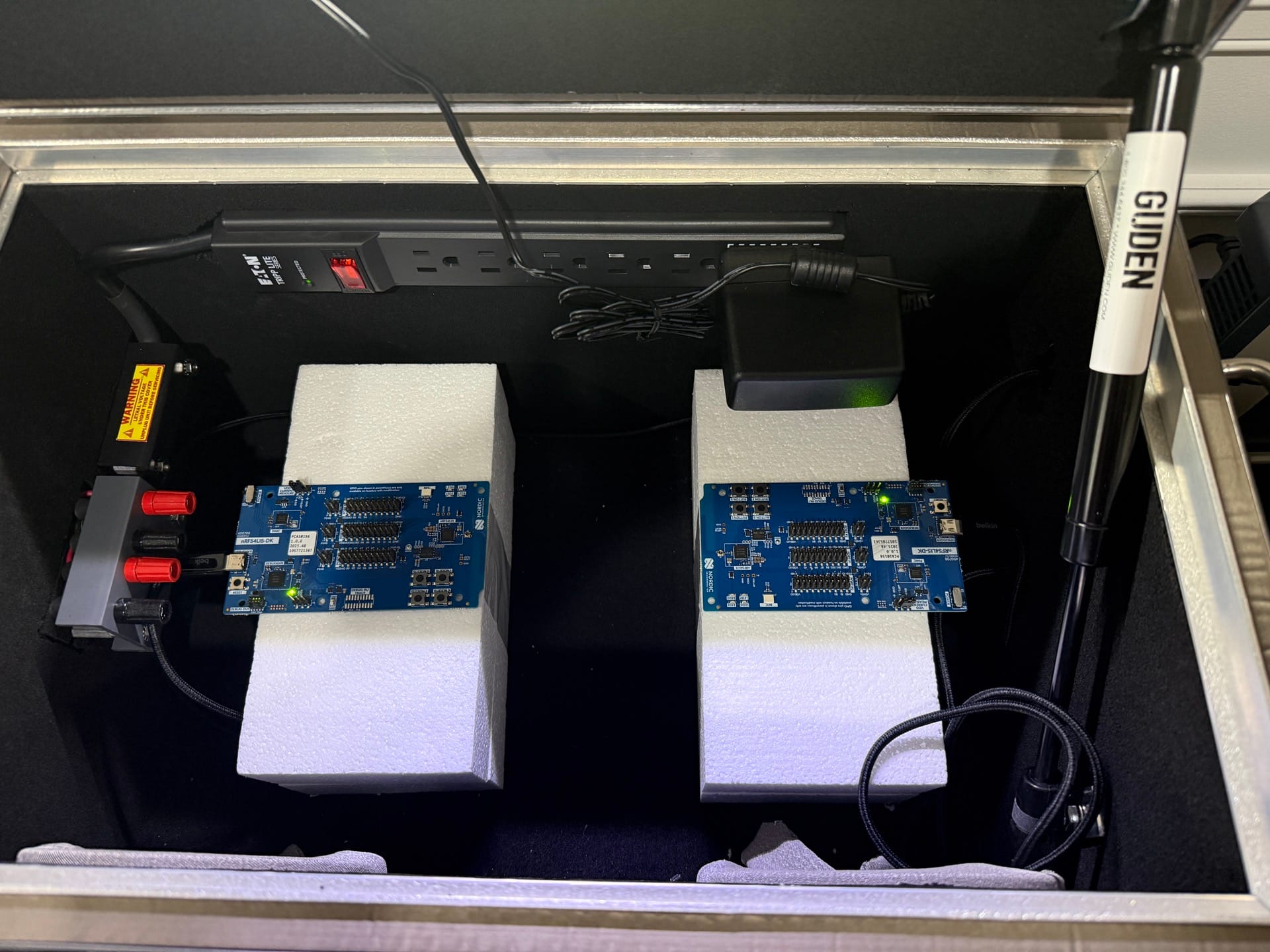
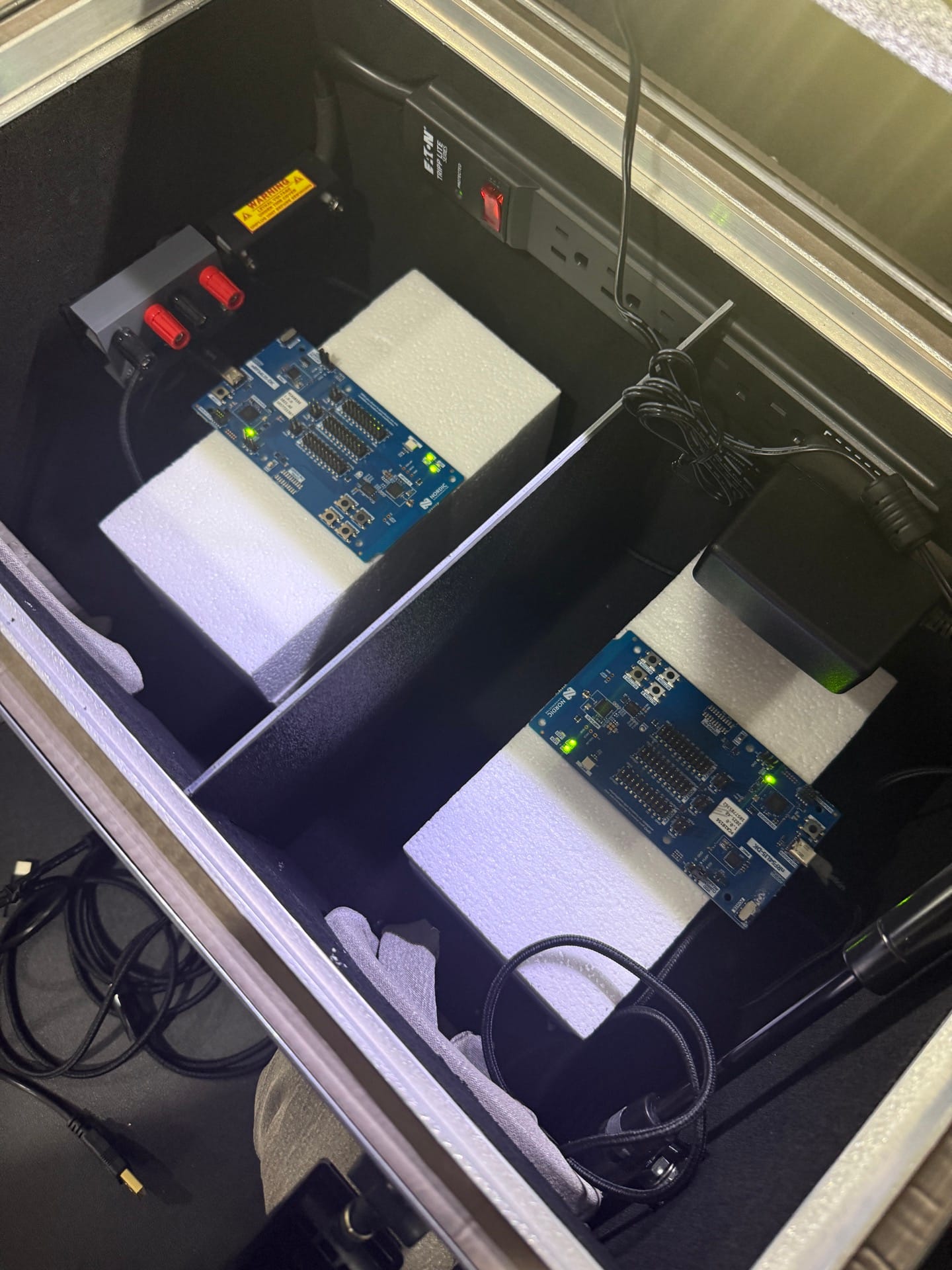
Let’s walk through the test setup. For this experiment, I used the Ramsey STE3000M RF shielded chamber (a $4,000 professional-grade enclosure) that we verified in Episode 0. The chamber demonstrated over 85 dB of shielding effectiveness at 2.4 GHz, giving us a controlled, interference-free environment where the only variable is the material we place between the transmitter and receiver.
Here’s the equipment and configuration:
- Transmitter: Nordic Semiconductor nRF54L15 DK, transmitting at 0 dBm on LE 1M PHY
- Separation: 4 inches between transmitter and receiver antennas
- Measurement: Received Signal Strength Indicator (RSSI) and Packet Error Rate (PER) monitored on the receiver
- Protocol: Bluetooth LE connection established, then material samples inserted between devices
- Chamber: Ramsey STE3000M with absorber foam to minimize reflections
The basic approach: establish a baseline measurement with nothing between the transmitter and receiver, then insert a material sample, measure again, and compare. With the devices only 4 inches apart and the transmitter set to 0 dBm, we had plenty of signal margin to detect even small changes in attenuation.
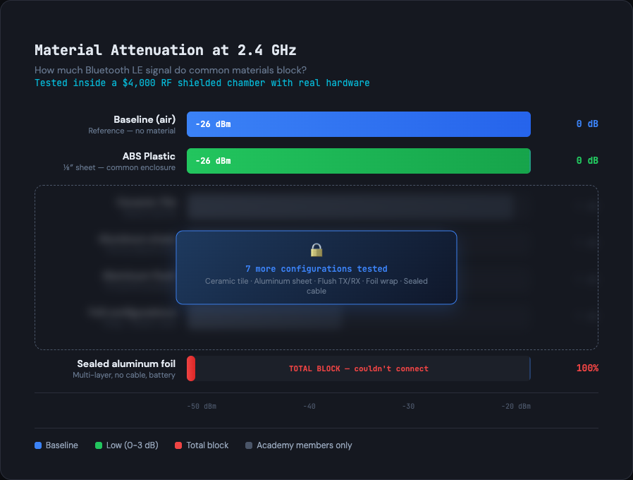
Our baseline measurement came in at -26 dBm RSSI with 0% Packet Error Rate (PER). This is the reference point: the signal strength with a clear line of sight between the two devices, no material in the way.
Let’s look at what we found.
The Results: Two Extremes
We tested multiple materials and configurations in total. For this public post, let’s dive into the two results that define the boundaries of what’s possible. They sit at opposite ends of the attenuation spectrum, and they tell you a lot about what to expect from your own designs.
ABS Plastic: Completely Transparent
ABS (Acrylonitrile Butadiene Styrene) is one of the most common enclosure materials for consumer electronics. It’s what most Bluetooth LE sensor housings, smart home devices, and wearable casings are made from. If you’ve 3D-printed a prototype enclosure, there’s a good chance it was ABS.
The result? ABS plastic is completely transparent to Bluetooth LE signals at 2.4 GHz.
With the ABS sample in place, we measured -26 dBm RSSI and 0% PER, identical to our baseline. That’s 0 dB of attenuation. The signal passed through the plastic as if it wasn’t there.
For practical purposes, an ABS enclosure adds zero measurable signal loss to your link budget. If you’re seeing range problems with a device in an ABS housing, the enclosure is not your problem. Look at your antenna design, TX power configuration, or the RF environment instead.
This is good news for the vast majority of consumer Bluetooth LE products. Your plastic enclosure is not degrading your RF performance.
Aluminum Foil Wrap: Total Blockage
Now let’s look at the other extreme. We wrapped one of the devices completely in aluminum foil (with no cable passthrough) to simulate a fully enclosed metal housing. The kind of scenario you’d encounter with a sealed metal enclosure, an equipment rack, or a foil-backed insulation panel.
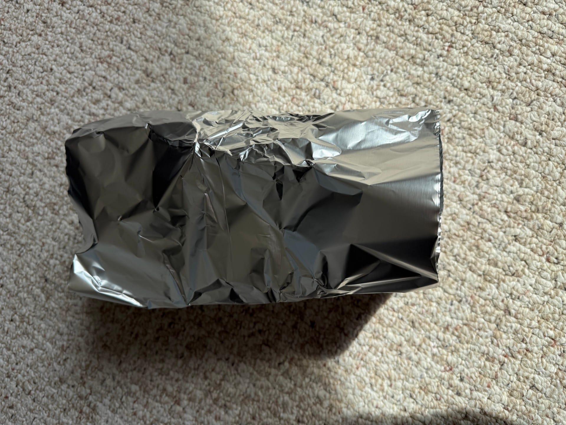
The result was decisive: the devices could not even establish a Bluetooth LE connection. Total blockage. Not degraded performance, not higher packet loss, simply no communication whatsoever.
This has real implications. If your device sits inside a metal enclosure (industrial sensors, equipment monitoring, automotive applications), you cannot rely on the signal radiating through the housing. You will need an external antenna, an RF window made from a non-metallic material, or a deliberate gap in the shielding.
I’ve seen developers discover this the hard way: prototype with a 3D-printed plastic case, everything works beautifully, then move to the production metal enclosure and the device goes completely silent. Having the data upfront prevents that expensive surprise.
The Surprising Middle Ground
Those two extremes are useful anchors: plastic is invisible, metal is an impenetrable wall. But the really interesting results live in between. We tested ceramic tile, multiple aluminum configurations (not just the full wrap), and discovered something genuinely unexpected about what happens when metal is near an antenna without fully enclosing it.
I’ll say this much: the relationship between metal proximity and signal degradation is not what most developers assume. The data revealed a phenomenon that goes beyond simple attenuation, and it has direct implications for how you position antennas relative to metal surfaces in your product designs.
The full Academy lesson for Episode 1 covers:
- All materials and configurations tested with exact RSSI values, PER numbers, and attenuation calculations
- A detailed comparison table showing how each configuration stacks up
- The antenna detuning discovery that changed how I think about metal near Bluetooth LE antennas
- Multiple aluminum configurations compared revealing that how you use metal matters as much as whether you use it
- Practical design guidelines for enclosure selection, antenna placement, and deployment strategy
Why Controlled Measurements Matter
You might be wondering: couldn’t I just test this at my desk? Set up two dev boards, put a piece of material between them, and compare the RSSI readings?
You could, but the results would be unreliable. In an open environment, the signal goes around the material, bounces off walls, and gets influenced by whatever Wi-Fi traffic happens to be present. Your “material attenuation” measurement would actually be a mixture of direct-path attenuation, multipath reflections, diffraction, and ambient interference.
The shielded chamber eliminates those confounding variables. The absorber foam minimizes internal reflections, the shielding blocks external interference, and fixed device positions ensure repeatable geometry. When we measure a difference with a material in place, we know it’s from the material, not from someone’s microwave oven turning on next door.
That’s the value of a $4,000 chamber. It turns “I think plastic is fine” into “I measured 0 dB attenuation through ABS at 2.4 GHz with 0% packet error rate.” One is a guess. The other is engineering.
Wrapping Up
In this post, we covered why material attenuation matters for Bluetooth LE product design, walked through the test setup inside the RF shielded chamber, and looked at two measured results that define the extremes: ABS plastic (completely transparent, 0 dB attenuation) and aluminum foil wrapping (total blockage, connection impossible).
Here are the key takeaways:
- Material attenuation at 2.4 GHz varies from zero to total blockage depending on the material, making it one of the most important variables in your link budget
- ABS plastic enclosures are completely transparent to Bluetooth LE signals (0 dB measured attenuation, 0% PER), so if you’re seeing range problems with a plastic-housed device, look elsewhere
- Metal enclosures can completely block Bluetooth LE signals to the point where a connection cannot even be established. Plan for external antennas or non-metallic RF windows
- Controlled measurements in a shielded chamber isolate the material’s effect from multipath, diffraction, and interference
- The middle ground between plastic and metal is where the most actionable (and surprising) data lives
You should now have a clearer picture of how materials at opposite ends of the spectrum affect Bluetooth LE signals, and why having real measured numbers matters for your product design decisions.
Stay tuned for the next episode, where we’ll continue testing more materials and configurations inside the chamber.


