

When it comes to Bluetooth Low Energy modules, chipsets and development kits, prices are only getting lower. Take for example the new nRF52840 USB dongle. The dongle costs only $10 and can serve as a great development kit with a few I/O peripherals including one button, two LEDs (one green, one RGB), and 15 GPIO pins.
The nRF52840 dongle is a compact USB dongle that's based on the nRF52840 chipset from Nordic Semiconductor. The dongle can be used in two main use cases:
- As a dongle that enables nRF Connect PC applications such as the Bluetooth Low Energy application (central and peripheral emulator), the nRF Cloud Gateway application, and the RSSI Viewer application.
- As a development kit that can run your own custom applications or the sample applications provided with the nRF52 SDK. These include Bluetooth Low Energy, Bluetooth mesh, Thread, ZigBee, 802.15.4, ANT and 2.4GHz proprietary applications.
Keep in mind that the dongle does not have debug capabilities, but rather only supports programming or communicating via the USB port. Also, as of the time of this tutorial, the nRF Sniffer application does not support the nRF52840 dongle, but this is inevitable to change. When this feature becomes available, this low-cost dongle will serve as a great sniffer especially for capturing Bluetooth 5 BLE traffic including long-range mode (Coded PHY), high-speed mode (2M PHY), and extended advertisements packets.
In today's blog post, we will cover how to use the dongle for running the Bluetooth Low Energy nRF Connect application as a central or a peripheral. In an upcoming post, we will go over how to use the dongle to run your own custom BLE application.
More info on the dongle can be found at the Nordic InfoCentral documentation website here: nRF52840 USB dongle.
If you're interested in buying it, check out this page.
Follow-up posts:
nRF Connect Bluetooth Low Energy application
The nRF Connect application on the desktop supports a few applications (with more being added continuously). It started out as a simple application but is now becoming the single hub for all desktop-based nRF applications. As of the writing of this tutorial, the applications included in the desktop nRF Connect app are:
- Bluetooth Low Energy application
- nRF Cloud Gateway application (experimental)
- Power Profiler
- Programmer (experimental)
- RSSI Viewer
Today we will be focusing on using the Bluetooth Low Energy application.
The different applications that support the dongle will automatically prompt you to update the dongle with the appropriate firmware that allows the application to interface with the dongle.
The Bluetooth Low Energy supports two modes of operation:
- As a BLE central device that can discover advertising devices (broadcasters and peripherals).
- As a BLE peripheral that advertises, allows connections, and exposes a GATT server. The GATT can be customized with SIG-adopted services and characteristics or your own custom services and characteristics.
Installing the nRF Connect and Bluetooth Low Energy Applications
To get started, follow these steps:
- Make sure you have the nRF52840 USB dongle connected to your computer
- Install the nRF Connect desktop application from this link. The application is available for Linux, macOS, and Windows.
- Once you have the application installed, launch the application. you will be presented with the following screen:
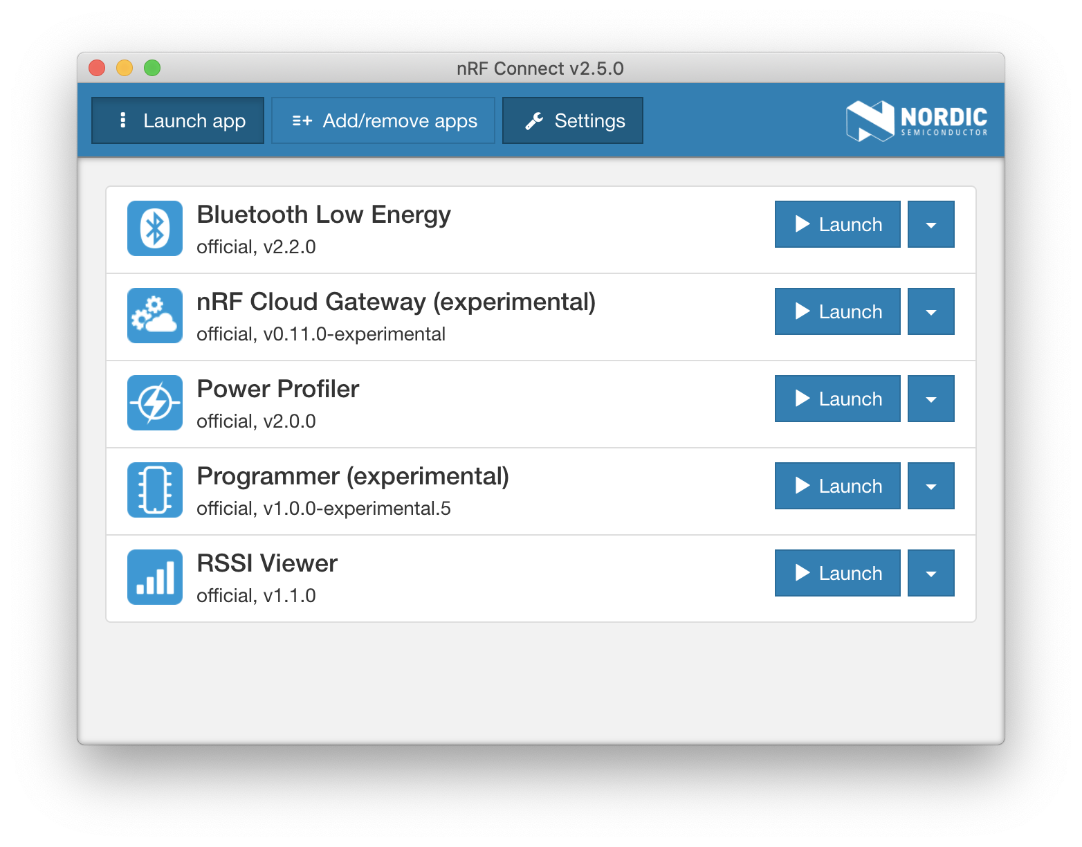
- Navigate to the Add/remove apps tab
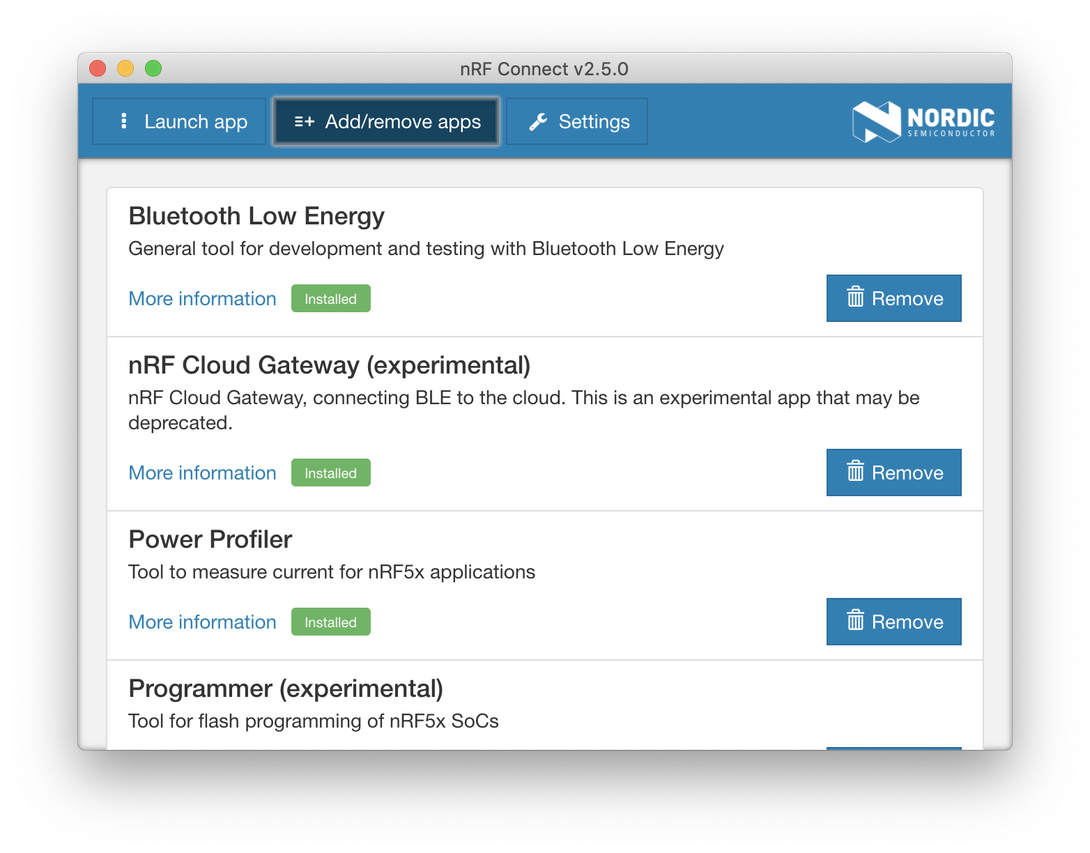
- Make sure that the Bluetooth Low Energy application is installed. If not, click the Install button.
- Make sure the application is up-to-date. Navigate to the Settings tab then click Check for updates now.
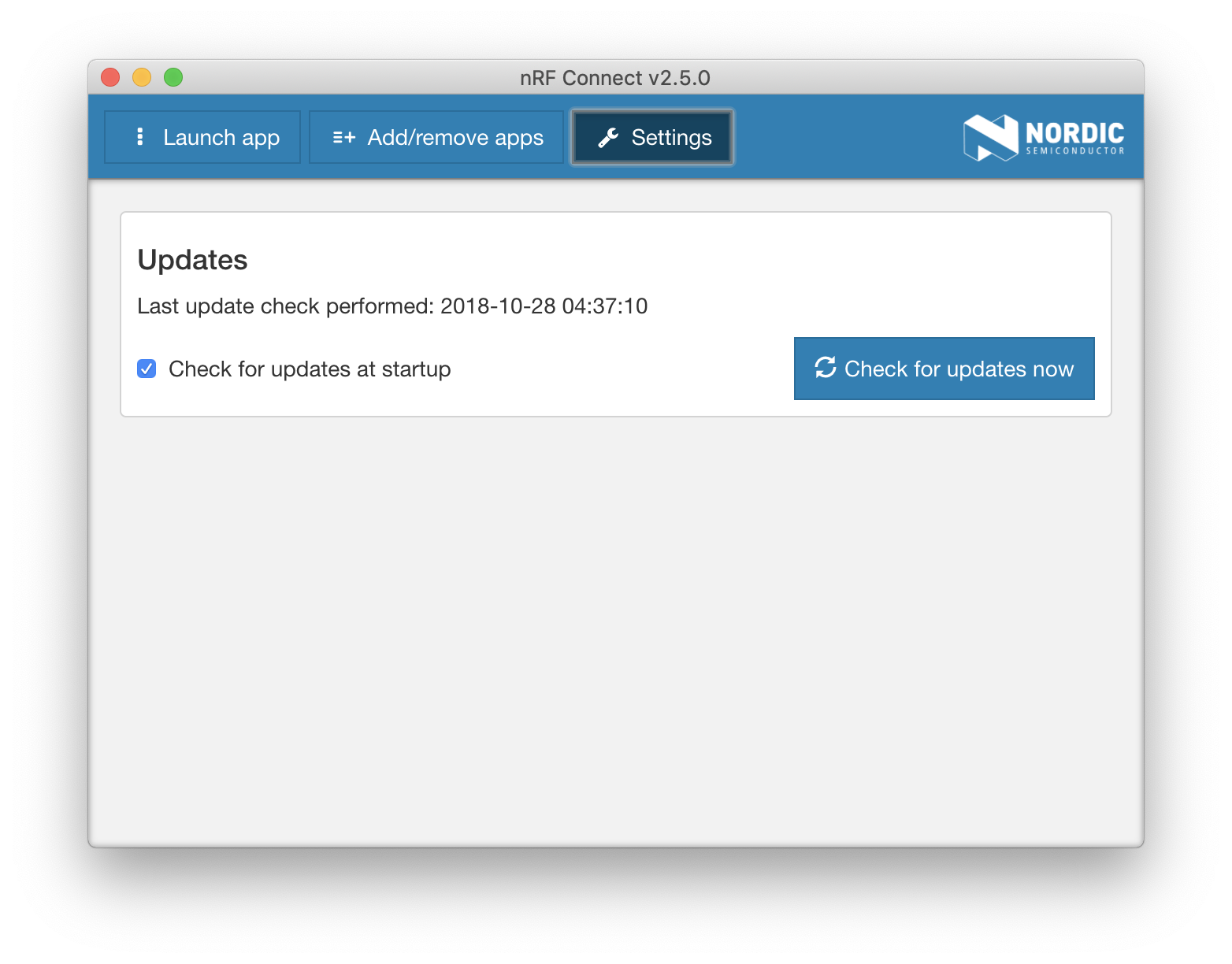
- Navigate back to the Add/remove apps tab. If there's an update available, click Update.
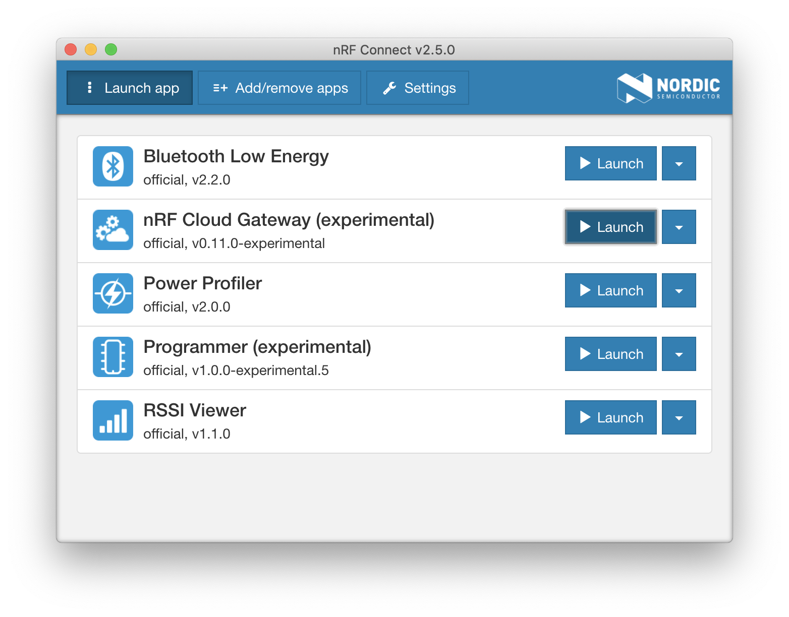
- Navigate back to the Launch app tab, and launch the Bluetooth Low Energy application.
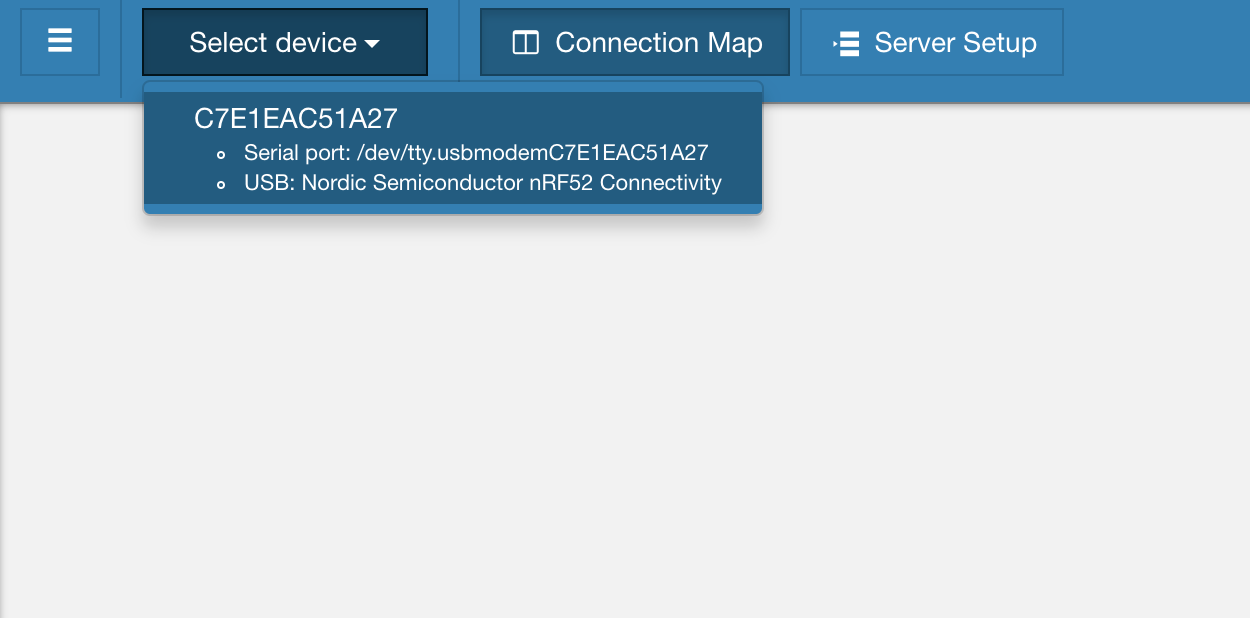
- If this is the first time you're using this application, or if you've used the dongle with another app or programmed it with your own application, you will have to update the dongle with the appropriate firmware that enables it to run the Bluetooth Low Energy application. To do this, select the device from the Select serial port drop-down menu and you will be prompted to update the firmware on the device:
- Once it's programmed correctly, you will see the following screen:
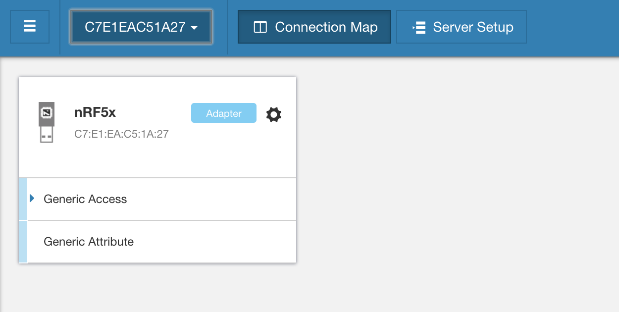
Now you're ready to run interface with the dongle and use it as either a BLE central or as a BLE peripheral.
BLE Central Mode
Whether you're testing a new feature of your BLE device or want to interact with an existing one, using an application that acts as a BLE central (aka central emulator apps) can help a lot.
It saves you from spending hours programming a custom application to perform your own testing. This is especially useful during the early phases of a project when the mobile companion app is not ready yet and may require a lot of effort to get it working.
There are two main aspects of acting as a central device:
- Discovering advertising devices in the surrounding area.
- Connecting to an advertising device (that allows connections). Usually, following a connection, the central will also interact with the peripheral's GATT server (and vice versa) via reads, writes, notifications, and indications on characteristics.
Let's cover each of these aspects and how to accomplish them using nRF Connect's Bluetooth Low Energy application.
Scanning for BLE peripherals
To perform a scan for advertising BLE devices:
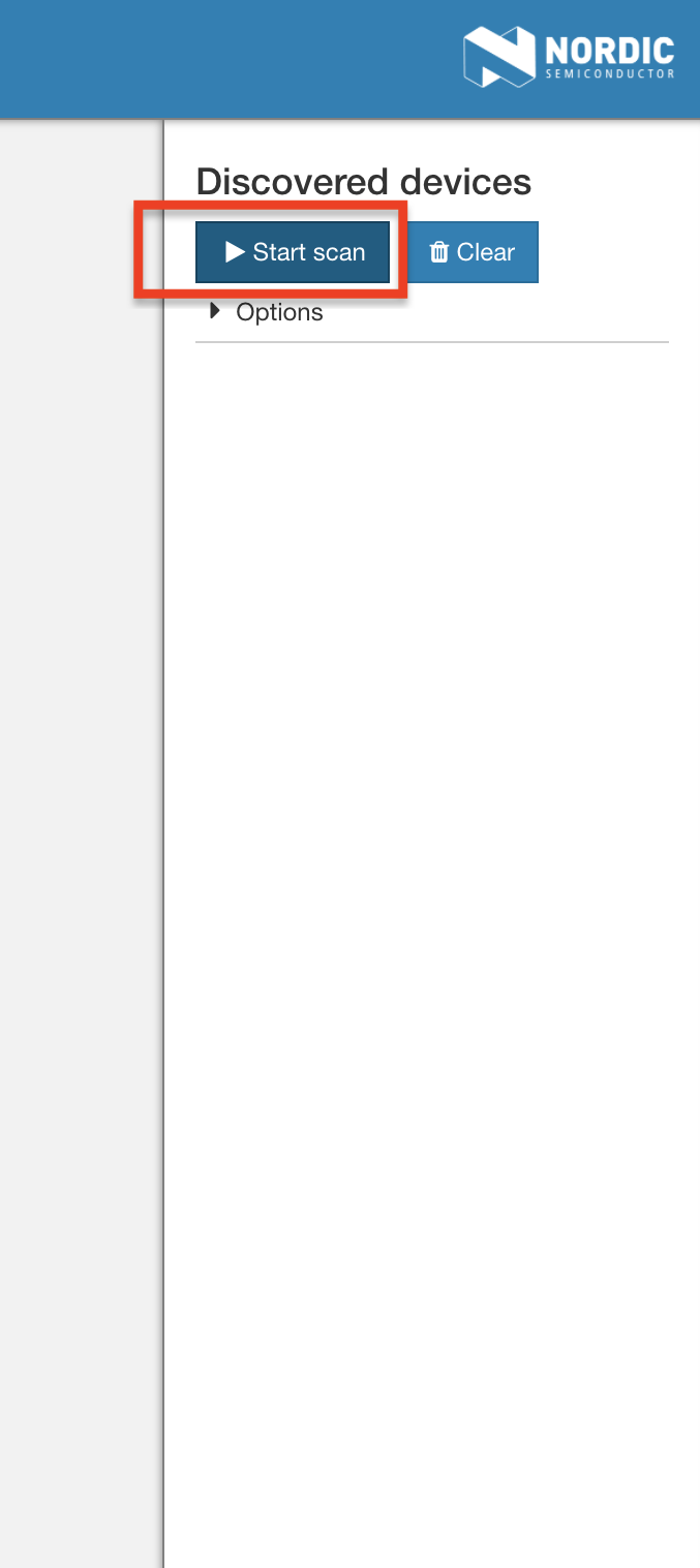
- Start by clicking the Start scan button.
- I find it helpful to sort the list of scanned devices by RSSI. You could do this by clicking Options then Sort by signal strength.
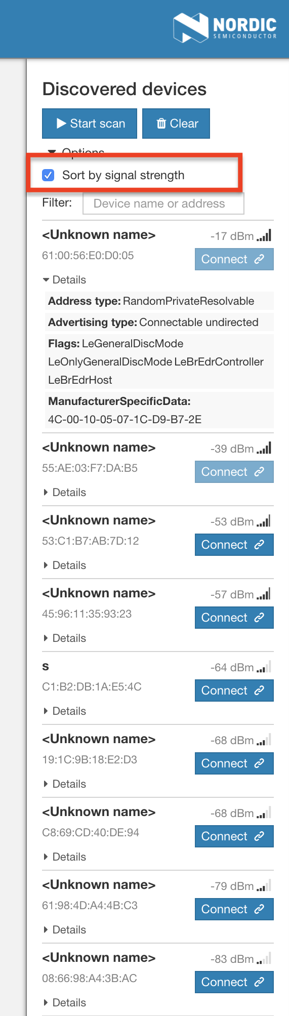
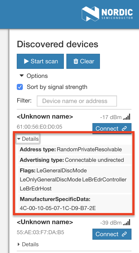
- To see more details about the advertising device, click the Details button. This will display the advertising data and any fields it contains.
Connecting to BLE peripherals
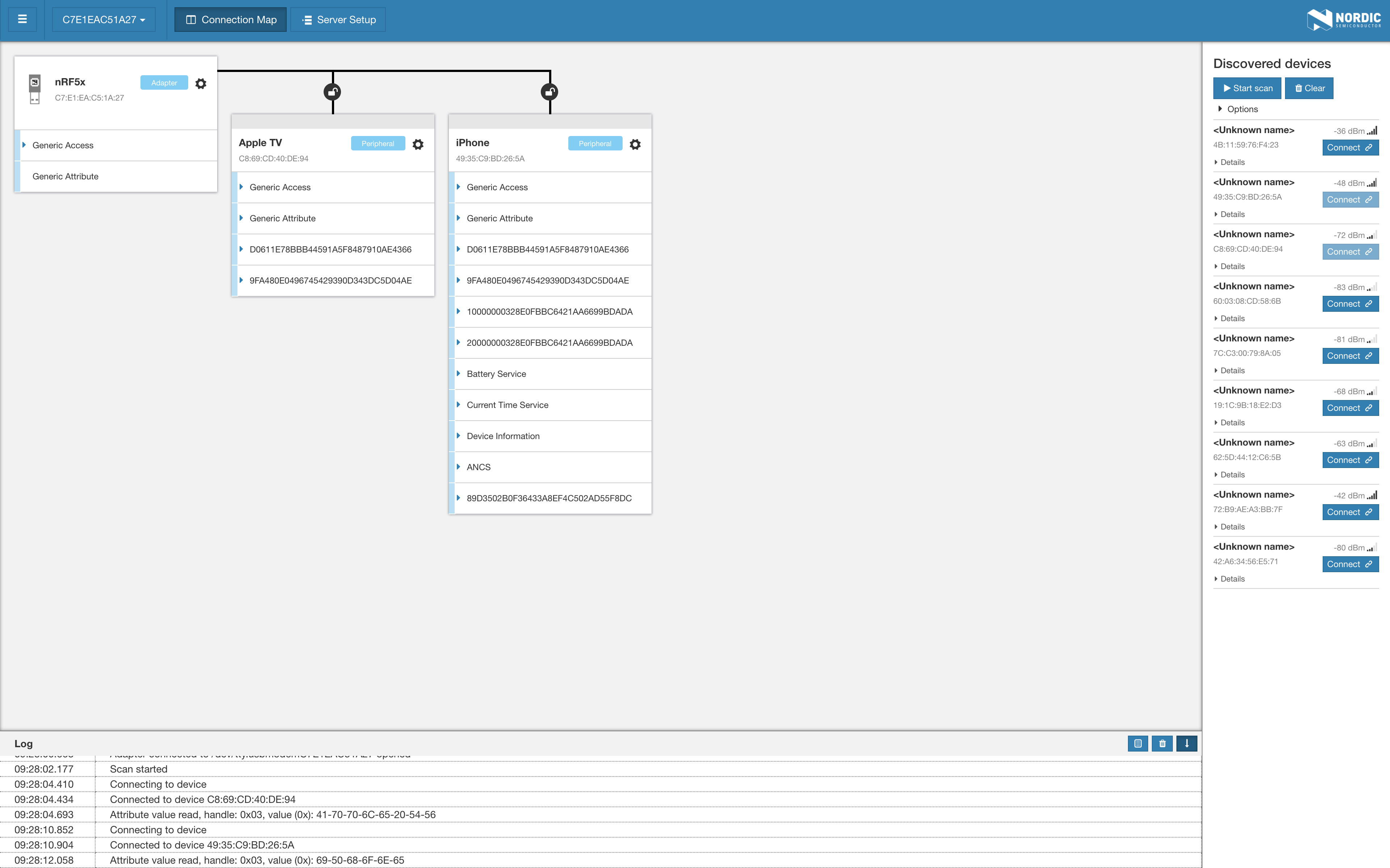
After scanning for devices, you can connect to a device by clicking the Connect button next to a device in the scan results. Once you're connected to a peripheral, you can browse and navigate the different services and characteristics exposed by the GATT server on the device.
nRF Connect's Bluetooth Low Energy app allows you to connect to multiple peripherals at the same time, and they will all be displayed in the same window:
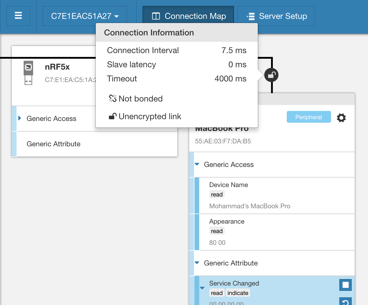
You could also see the parameters and properties of the connection such as:
- Connection interval
- Slave latency
- Supervision timeout
- Bonding status
- Pairing status
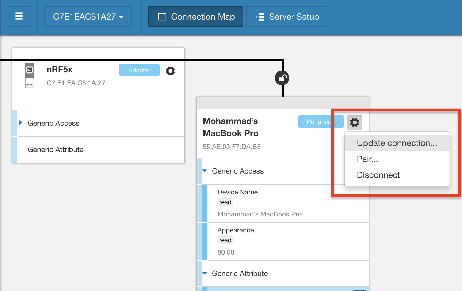
Another feature available is the ability to change the properties of the connection (since the dongle acts in the central role, and hence it controls the parameters) such as:
- Connection parameters
- Initiating pairing
- Disconnecting
Once you're connected to a peripheral, you can now interact with the device's GATT server. For example, you could read, write and enable/disable notifications and indications.
Reading characteristics
To read a characteristic, click on the characteristic of interest then click on the "reload" icon:
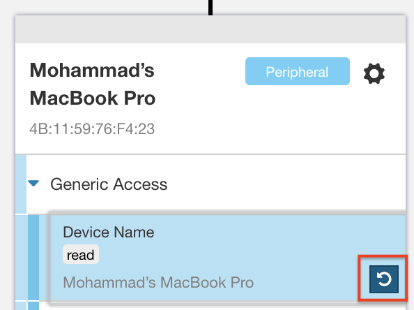
Now the new value (if any) will be updated.
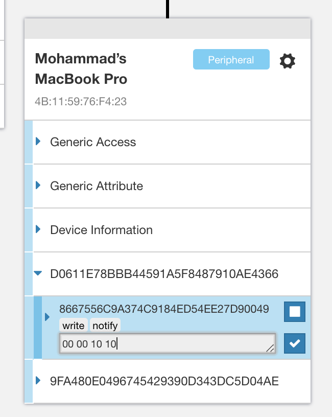
Writing to characteristics
To write to a characteristic, select the characteristic of interest, then click on the text input box located under the properties (read, write, indicate, etc.). Then enter the value you wish to write, and press the checkmark button:
BLE Peripheral Mode
To set up the dongle to act as a peripheral, we first need to configure the different parameters and services and characteristics exposed by the GATT server. To do this, navigate to the Server Setup tab:
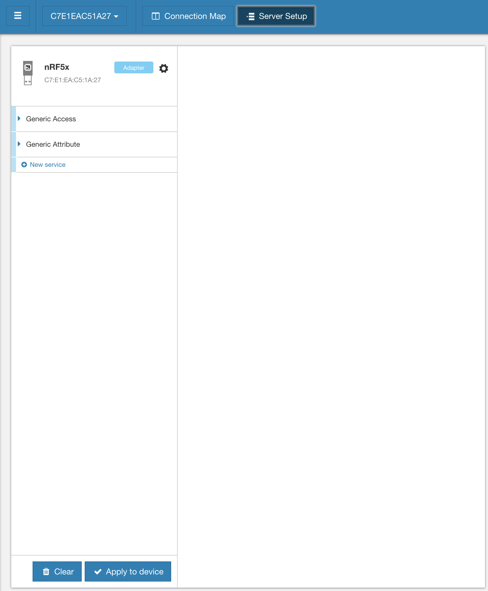
You'll notice that the Generic Access service already exists since it's a mandatory service. Within the service, you'll find three characteristics defined:
- Device Name
- Appearance
- Peripheral Preferred Connection Parameters
You can customize each of these characteristics by clicking on them.
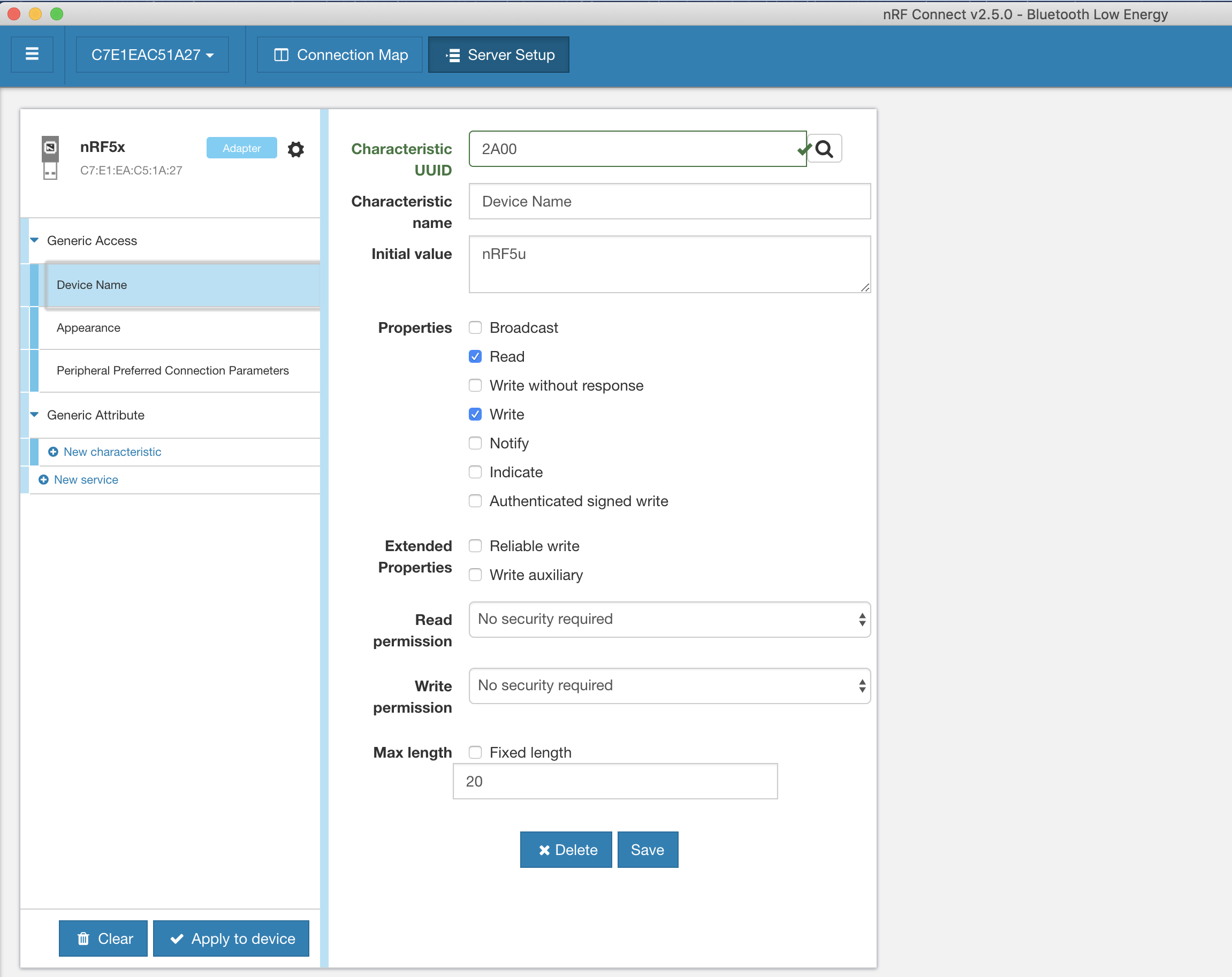
You can also add services and characteristics of your own.
Once you're done with the customizations, click the "Apply to device" button.
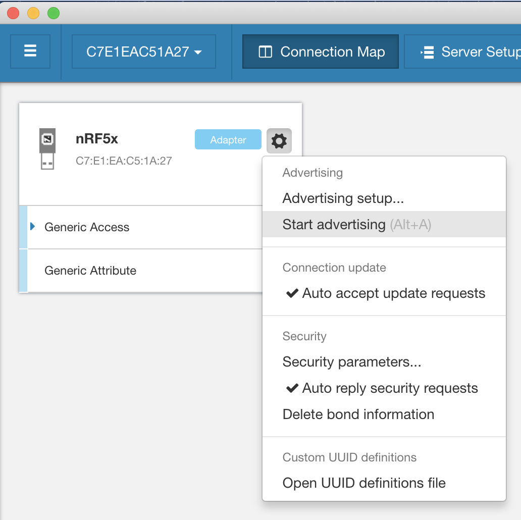
Now you can go back to the Connection Map tab. Click the gear button next to the nRF5u dongle listing, then click on Start advertising.
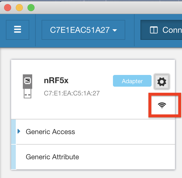
Once it starts advertising, a wireless icon will be displayed:
To verify the device is advertising and working properly, you can use a BLE client emulator app on a mobile phone such as Nordic nRF Connect or LightBlue Explorer.
Peripheral mode example
Let's go ahead and set up the nRF52 USB dongle to include the Battery service and Battery Level characteristic, then connect and interact with it from a mobile app. For the mobile app I will be using LightBlue.
Here's a video showing the whole process:
As you can see, with just a few quick steps we can set up a peripheral, discover it and connect to it from a mobile app. We can also see that changing the value of a characteristic on the device side (via the nRF Connect app on the PC) is reflected and can be seen on the mobile side.
Summary
In this tutorial, we introduced the nRF52840 USB dongle. We then talked about the two main use cases of the dongle: as a tool for nRF Connect apps or as a general nRF development kit. Today's tutorial focused on using the dongle as an nRF Connect tool. In an upcoming follow-up tutorial, we'll cover the other use case: how to use the dongle as a general nRF development kit to run your own custom applications.


